What Is a Distributed Power Generation Gearbox?
A Distributed Power Generation Gearbox transfers mechanical power within smaller, locally connected energy systems. These systems may use wind turbines, biogas engines, small hydropower units, or waste-heat equipment. Unlike a gearbox serving one large central plant, it often operates across multiple sites and changing load conditions. Its role is simple to describe, but demanding in practice.
Inside the housing, gears adjust speed, torque, or rotation direction between the prime mover and generator. A wind turbine may turn slowly while its generator requires a much higher speed. The Distributed Power Generation Gearbox bridges that difference through carefully selected gear ratios. Bearings, lubrication channels, seals, and cooling surfaces must work together. A minor oil leak can become a serious maintenance signal.
Engineers usually assess rated torque, shock loads, efficiency, vibration, noise, and service access before selecting equipment. Field experience also matters. Dust, temperature swings, grid interruptions, and irregular fuel supply can change gearbox behavior. A laboratory rating cannot describe every operating site. That assumption can fail.
Reliable inspection includes checking lubricant condition, tooth wear, bearing temperature, and vibration trends. Digital sensors can support this work, but they do not replace practical judgment. A strange sound still deserves attention. No design is perfect.
Understanding this equipment requires more than memorizing a definition. It means connecting gearbox design with generator requirements, site conditions, maintenance planning, and long-term reliability. This article explains how a Distributed Power Generation Gearbox works, where it is used, and which technical details deserve closer review.
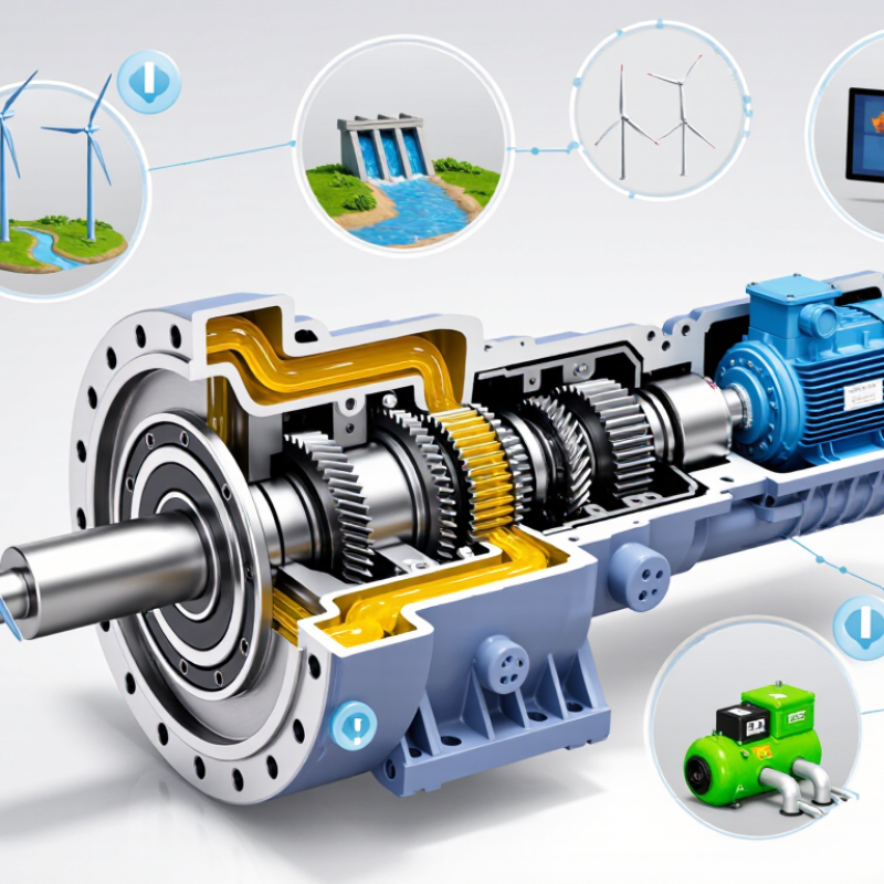
Definition and Core Purpose of a Distributed Power Generation Gearbox
A distributed power generation gearbox is a mechanical transmission used in local energy systems. It connects a prime mover, such as an engine, turbine, or water wheel, to a generator. Its core purpose is to match speed and torque between these components. This allows the generator to operate within its designed electrical range.
In practical installations, the gearbox must handle changing loads, vibration, heat, and frequent starts. A well-selected unit transfers power smoothly while limiting stress on shafts, bearings, and generator parts. It can also improve system flexibility when several small generation units serve nearby buildings or industrial equipment. However, a simple definition can hide important design risks. Efficiency may decrease when the gearbox runs far below its rated load. Noise and backlash can also become serious maintenance concerns.
Tips: Check the required input speed, output speed, torque, duty cycle, and operating temperature. Review lubrication access and inspection intervals before installation. Measure vibration during commissioning, not only after a fault appears. Leave room for alignment tools and replacement parts. In my view, designers sometimes focus too heavily on peak power. Average load and start-up conditions deserve equal attention. A gearbox that looks oversized on paper may still perform poorly under unstable operating patterns.
What Is a Distributed Power Generation Gearbox? - Definition and Core Purpose of a Distributed Power Generation Gearbox
| Data Dimension | Definition or Specification | Practical Importance |
|---|---|---|
| Definition | A distributed power generation gearbox is a mechanical transmission unit used in a generator system located close to the electrical load or energy source. | It transfers and adapts rotational power so locally installed generation equipment can operate at the required speed and torque. |
| Primary Purpose | To match the speed and torque of a prime mover with the operating requirements of an electrical generator. | Proper matching improves generator operation, power transmission, equipment compatibility, and overall system reliability. |
| Typical Distributed Generation Sources | Small wind turbines, microturbines, reciprocating-engine generator sets, biomass systems, and certain hydroelectric units. | The gearbox design depends on the source’s speed range, torque profile, duty cycle, and mechanical input characteristics. |
| Main Mechanical Function | It can increase rotational speed, reduce rotational speed, change torque, and transmit motion between shafts. | This allows a relatively slow or variable-speed prime mover to drive a generator within its intended operating range. |
| Speed Conversion | A speed-increasing gearbox raises the generator shaft speed above the input shaft speed; a reduction gearbox lowers it. | Speed conversion supports the generator’s required rotational speed without requiring the prime mover to operate at that same speed. |
| Torque Relationship | Ignoring losses, mechanical power remains approximately constant, so increasing speed generally reduces torque and reducing speed generally increases torque. | Correct torque conversion helps prevent overloads, excessive wear, and unstable generator operation. |
| Common Gear Elements | Gears, shafts, bearings, seals, housing, lubrication passages, couplings, and, in some designs, clutches or braking components. | Each component contributes to power transmission, alignment, load support, heat control, and protection from contamination. |
| Gear Type | Possible arrangements include spur, helical, bevel, planetary, or combined gear stages, depending on the application. | Gear geometry affects load capacity, noise, efficiency, packaging, shaft arrangement, and maintenance requirements. |
| Power Rating | The required rating is determined by transmitted mechanical power, rotational speed, torque, duty cycle, starting conditions, and design safety factors. | A gearbox must be sized for continuous operation as well as temporary overloads, shock loads, and expected operating variations. |
| Efficiency | Gearbox efficiency is less than 100% because of gear meshing, bearing friction, seal drag, oil churning, and other mechanical losses. | Higher efficiency reduces fuel or resource consumption, heat generation, operating cost, and the cooling burden on the system. |
| Speed Range | The allowable input and output speed range must remain within the limits of the gearbox, generator, prime mover, bearings, and lubrication system. | Operating outside the approved range can cause overheating, vibration, lubrication failure, or premature component damage. |
| Distributed-System Location | The generation unit is installed near the point of consumption, the energy resource, or a local distribution network rather than only at a central power plant. | Local generation can reduce transmission distance and support resilience, local voltage management, and energy availability. |
| Electrical Compatibility | The gearbox itself is mechanical, but its output speed must be compatible with the generator and the required electrical frequency or power-conversion system. | Correct mechanical speed supports stable electrical production and helps the generator or converter operate within its design limits. |
| Lubrication | Lubrication may use splash, bath, forced circulation, or another method selected according to speed, load, temperature, and installation orientation. | Adequate lubrication limits friction, wear, corrosion, and heat while extending gear and bearing service life. |
| Monitoring Parameters | Common measurements include vibration, oil temperature, oil condition, shaft speed, torque, bearing temperature, and abnormal noise. | Condition monitoring can identify misalignment, gear damage, bearing defects, lubrication problems, and overheating before major failure occurs. |
| Maintenance Requirements | Maintenance typically includes oil inspection or replacement, leakage checks, alignment verification, vibration analysis, fastener inspection, and periodic component assessment. | A planned maintenance program helps maintain efficiency, reduce unplanned downtime, and protect connected generation equipment. |
| Core Value in Distributed Power Generation | The gearbox provides the mechanical interface between a local energy source and the generator when their speed and torque requirements differ. | It enables practical integration of diverse local generation technologies while supporting reliable and efficient power production. |